 Tweet
Tweet
GIGABYTE GA-P67A-UD4 Review Featuring 6Gb/s RAID Testing

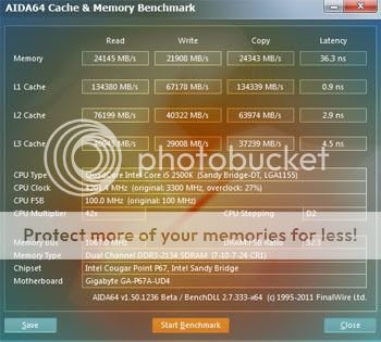
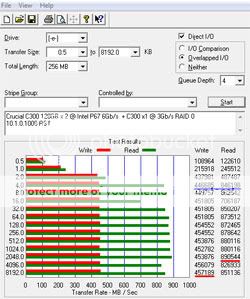
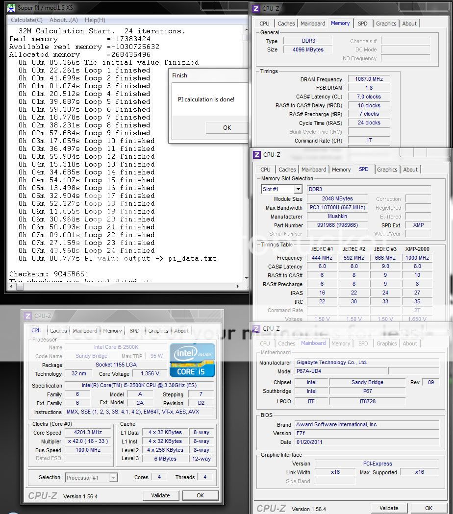
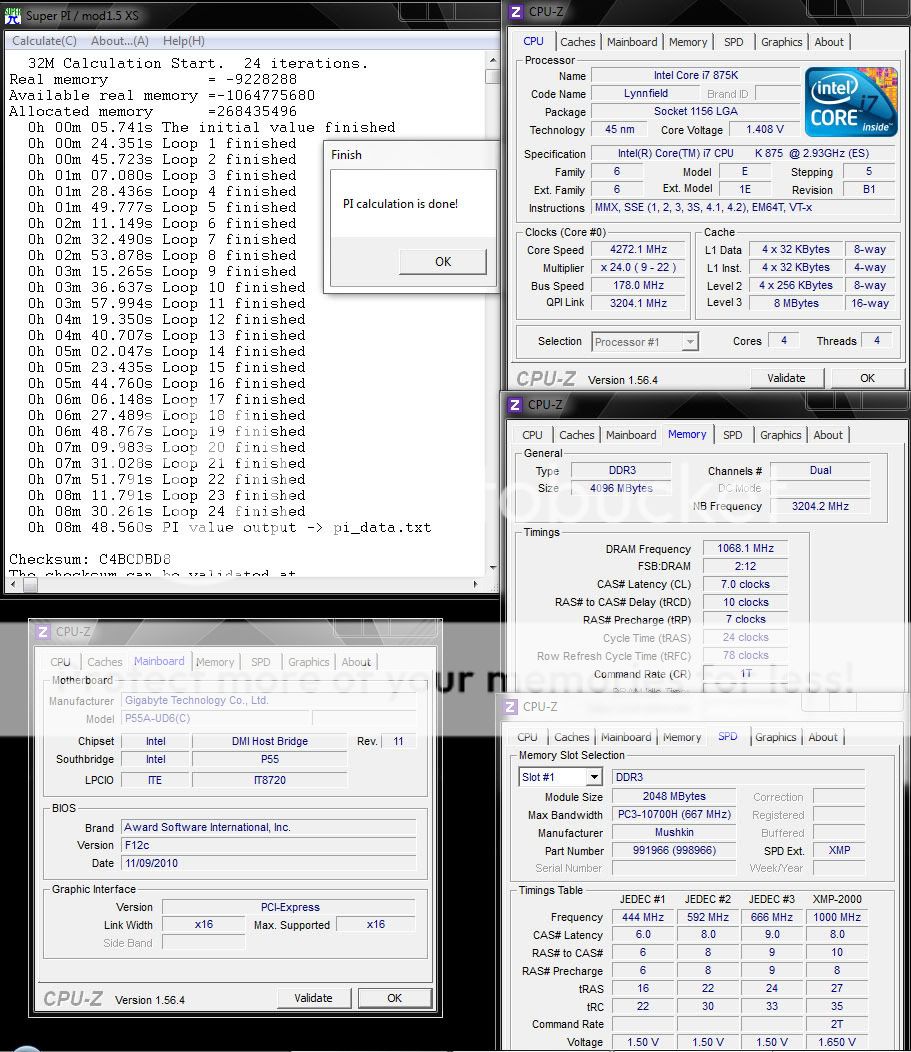
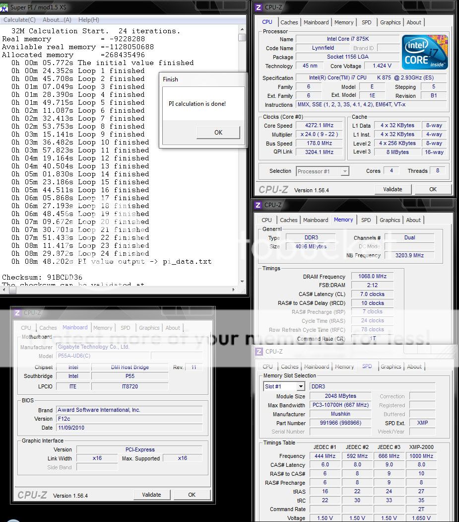
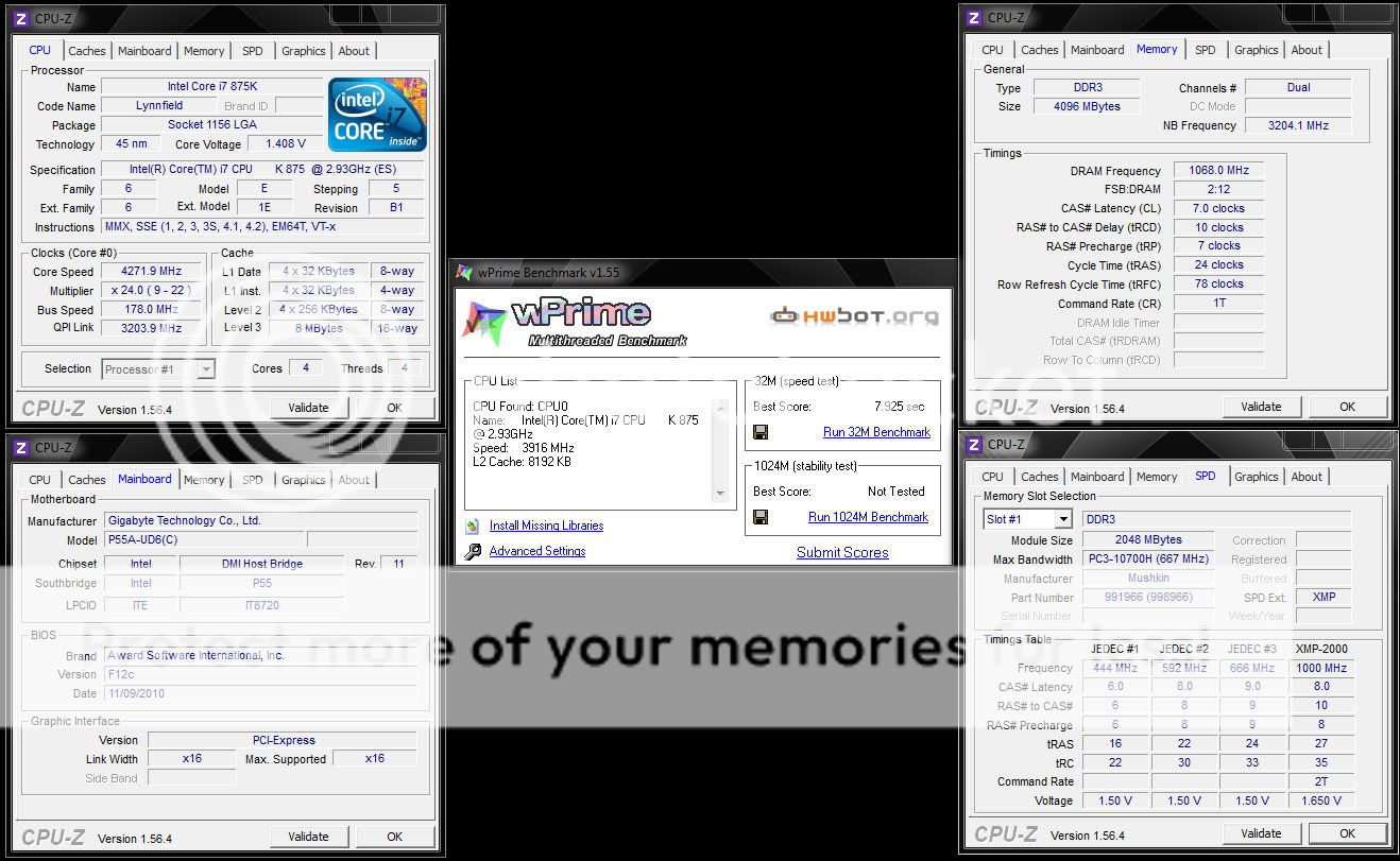
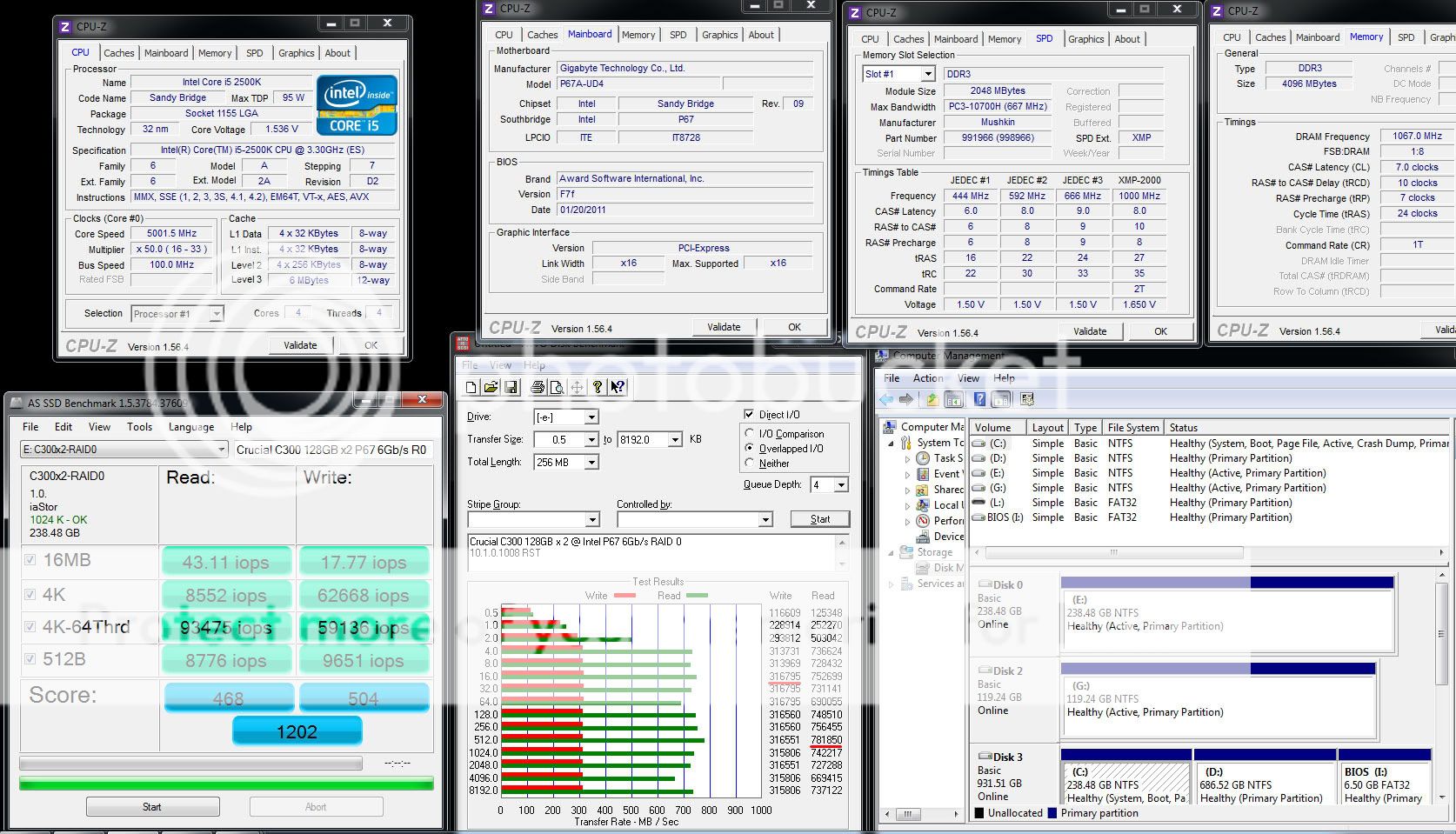
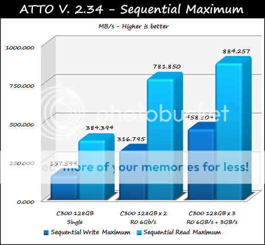
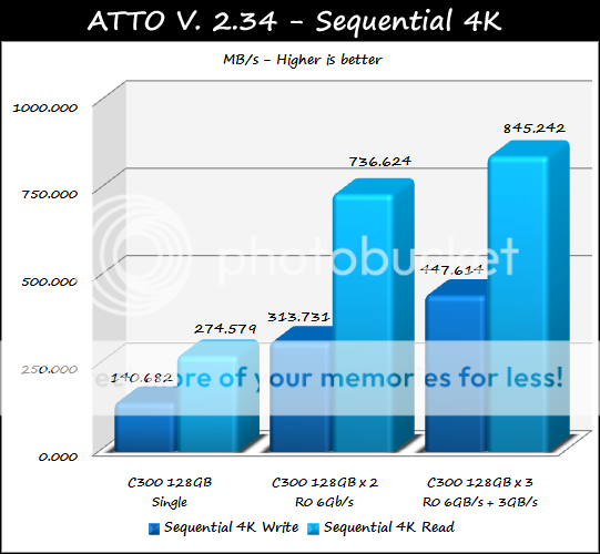
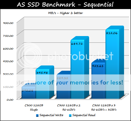
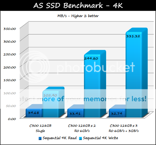
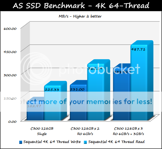
GIGABYTE's latest mid-range offering, the GA-P67A-UD4, has a lot to offer the end user at a very respectable lower price range. I am excited to see how the new chipset stacks up against last years P55 motherboards, this review will be covering many aspects of performance offered by the P67A-UD4 in comparison to the older P55 chipset. This will entail several benchmarks that cover processor and memory performance, and graphical performance comparisons will be included as well. I will also be showing how the new Intel based SATA 6Gb/s performs with the insanely fast Crucial C300 6Gb/s SSD, this is one of the features I looked forward to most in the P67 series.
Midway through my data collection process for this review I learned of the Intel Series 6 Chipset recall, due to a faulty SATA 3Gb/s component in the P67 chipset. This design flaw does not affect overall motherboard performance in any way, and is only limited to affecting the 3Gb/s SATA ports. This will be discussed in further detail at the end of the review, for now we will venture onward and see how the GA-P67-UD4 stacks up against last years P55 chipset.
Let's learn a little bit about GIGABYTE before we get into the review.
Originally posted by GIGABYTE
Introducing the Gigabyte GA-P67A-UD4 motherboard
Features:

Product Specification:
CPUChipsetMemory
1. 4 x 1.5V DDR3 DIMM sockets supporting up to 32 GB of system memory
* Due to Windows 32-bit operating system limitation, when more than 4 GB of physical memory is installed, the actual memory size displayed will be less than 4 GB.
2. Dual channel memory architecture
3. Support for DDR3 2133/1866/1600/1333/1066 MHz memory modules
4. Support for non-ECC memory modules
5. Support for Extreme Memory Profile (XMP) memory modules
Multi-Graphics Technology
Support for ATI CrossFireX™/NVIDIA SLI technology
AudioLAN
1 x Realtek RTL8111E chip (10/100/1000 Mbit)
Expansion Slots
1. 1 x PCI Express x16 slot, running at x16 (PCIEX16)
* For optimum performance, if only one PCI Express graphics card is to be installed, be sure to install it in the PCIEX16 slot.
2. 1 x PCI Express x16 slot, running at x8 (PCIEX8) * The PCIEX8 slot shares bandwidth with the PCIEX16 slot. When the PCIEX8 slot is populated, the PCIEX16 slot will operate at up to x8 mode.
3. 3 x PCI Express x1 slots
(All PCI Express slots conform to PCI Express 2.0 standard.)
4. 2 x PCI slots
Storage Interface
Chipset:
1. 2 x SATA 6Gb/s connectors (SATA3_0, SATA3_1) supporting up to 2 SATA 6Gb/s devices
2. 4 x SATA 3Gb/s connectors (SATA2_2, SATA2_3, SATA2_4, SATA2_5) supporting up to 4 SATA 3Gb/s devices
3. Support for SATA RAID 0, RAID 1, RAID 5, and RAID 10
* When a RAID set is built across the SATA 6Gb/s and SATA 3Gb/s channels, the system performance of the RAID set may vary depending on the devices being connected.
Marvell 88SE9128 chip:
1. 2 x eSATA 6Gb/s connectors on the back panel supporting up to 2 SATA 6Gb/s devices
2. Support for SATA RAID 0 and RAID 1
USB
Chipset:
1. Up to 14 USB 2.0/1.1 ports (8 on the back panel, 6 via the USB brackets connected to the internal USB headers)
2 x Renesas D720200 chips:
1. Up to 4 USB 3.0/2.0 ports (2 on the back panel, 2 via the USB brackets connected to the internal USB headers)
Internal I/O Connectors
1. 1 x 24-pin ATX main power connector
2. 1 x 8-pin ATX 12V power connector
3. 2 x SATA 6Gb/s connectors
4. 4 x SATA 3Gb/s connectors
5. 1 x CPU fan header
6. 2 x system fan headers
7. 1 x power fan header
8. 1 x front panel header
9. 1 x front panel audio header
10. 1 x S/PDIF Out header
11. 3 x USB 2.0/1.1 headers
12. 1 x USB 3.0/2.0 header
13. 1 x serial port header
14. 1 x clearing CMOS jumper
Back Panel Connectors
1. 1 x PS/2 keyboard/mouse port
2. 1 x coaxial S/PDIF Out connector
3. 1 x optical S/PDIF Out connector
4. 8 x USB 2.0/1.1 ports
5. 2 x USB 3.0/2.0 ports
6. 2 x eSATA 6Gb/s ports
7. 1 x RJ-45 port
8. 6 x audio jacks (Center/Subwoofer Speaker Out/Rear Speaker Out/ Side Speaker Out/Line In/Line Out/Microphone)
Form Factor
ATX Form Factor; 30.5cm x 24.4cm
For full features and product specifications please visit the GA-P67A-UD4 product web page:
GIGABYTE P67A-UD4 Overview
Product Images:
Packaging & Accessories


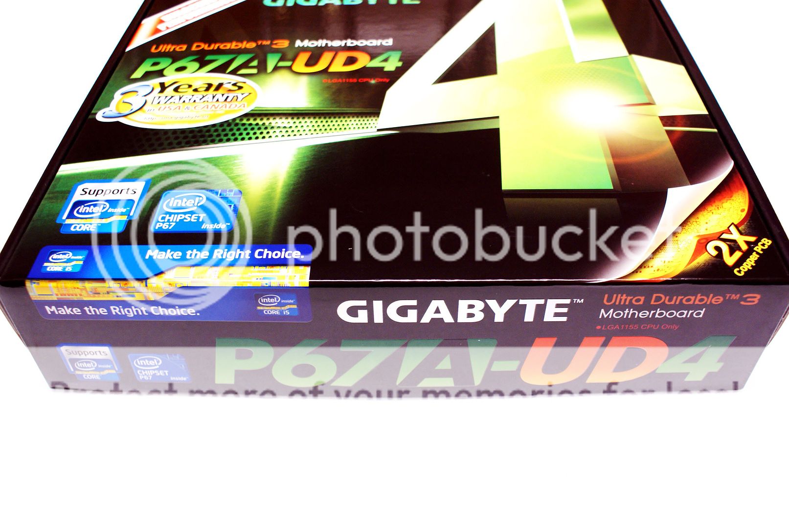
The front of the UD4 packaging is designed mainly in green and black, noting this is a Ultra Durable 3 motherboard and the model name, 2X Copper PCB, and that the board offers unlocked performance. There is also a few Intel logos indicating this is a P67 series chipset motherboard. Three year warranty is also noted on the front of the box, this is for USA and Canada only.
On the back of the box many of the motherboard features are detailed. GIGABYTE's main technology points described are Ultra Durable 3 (Featuring 2x Copper PCB), on-board 333 acceleration (USB 3.0, 3X USB Power delivery, and SATA 3.0). 3-way graphics is noted as well, along with ON/OFF charge, Smart 6, 50,000 hour capacitors utilized, dual BIOS, Auto Green, and XHD (Xtreme Hard Drive).
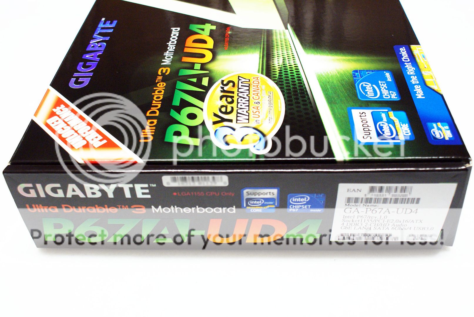
On the bottom of the box the label simply shows the model name again, along with Intel logos. On the side you have much of the same logos again, and the product UPC label indicating some of the product specifications, serial numbers, and the product revision number.
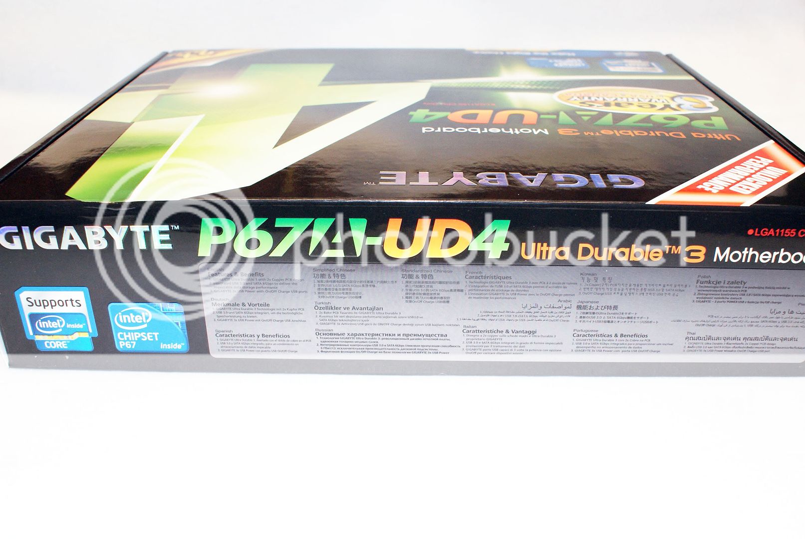
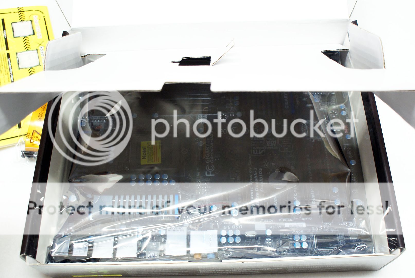
On the top of the box, in several languages, 3 major benefits of the board are noted (Ultra Durable 3, USB3 and SATA 6Gb/s, and USB ON/OFF charge for phones and other USB Devices). Inside the box under the included accessories we find a protective inner flap that securely houses the motherboard underneath.
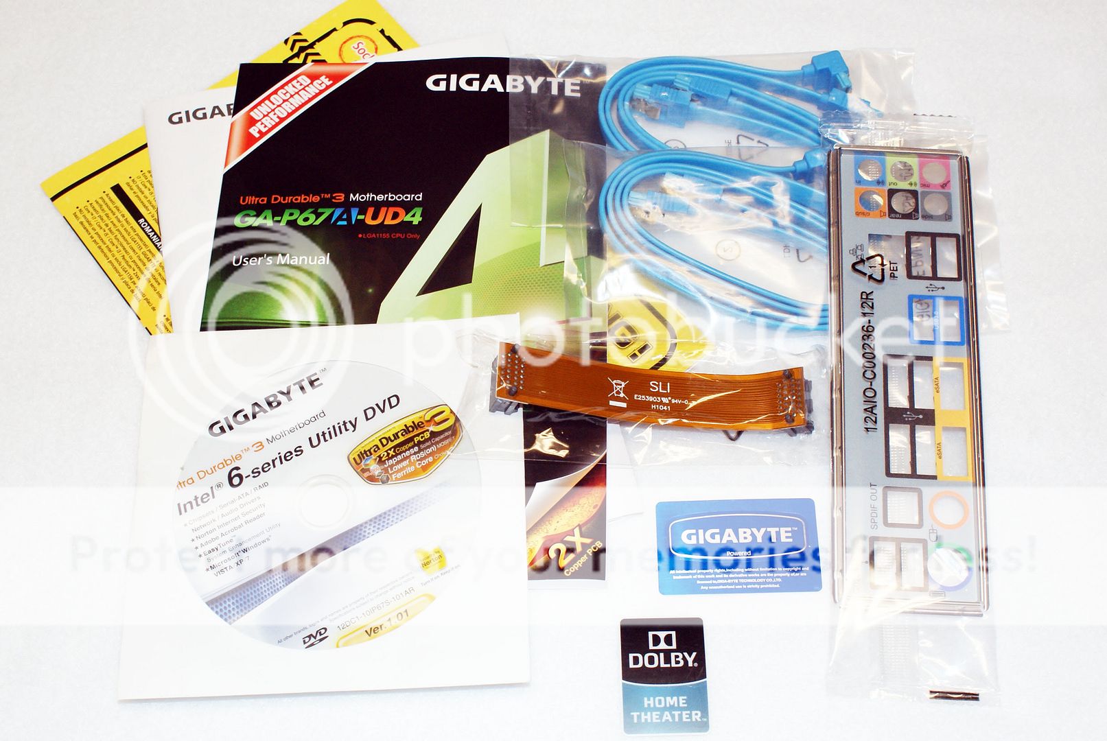
Included accessories with this motherboard are blue SATA cables, an SLI cable, I/O shield, and the usual motherboard manuals, install CD, and stickers.
Motherboard


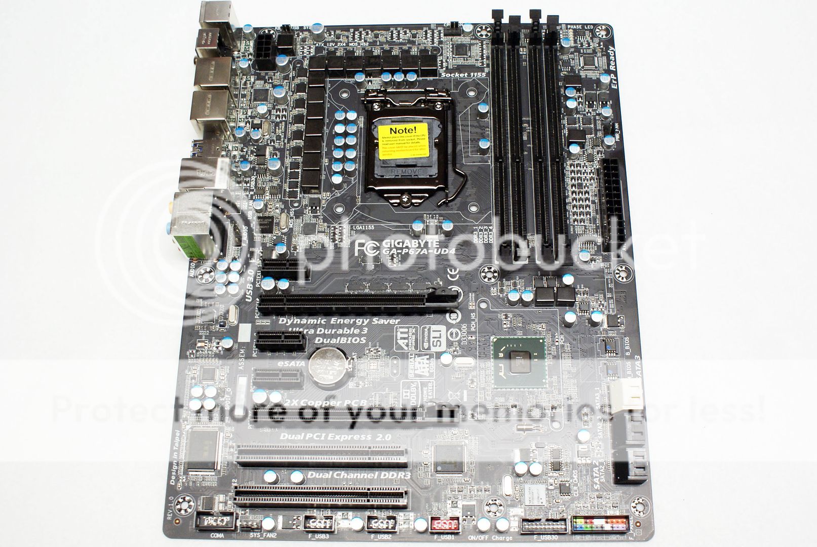
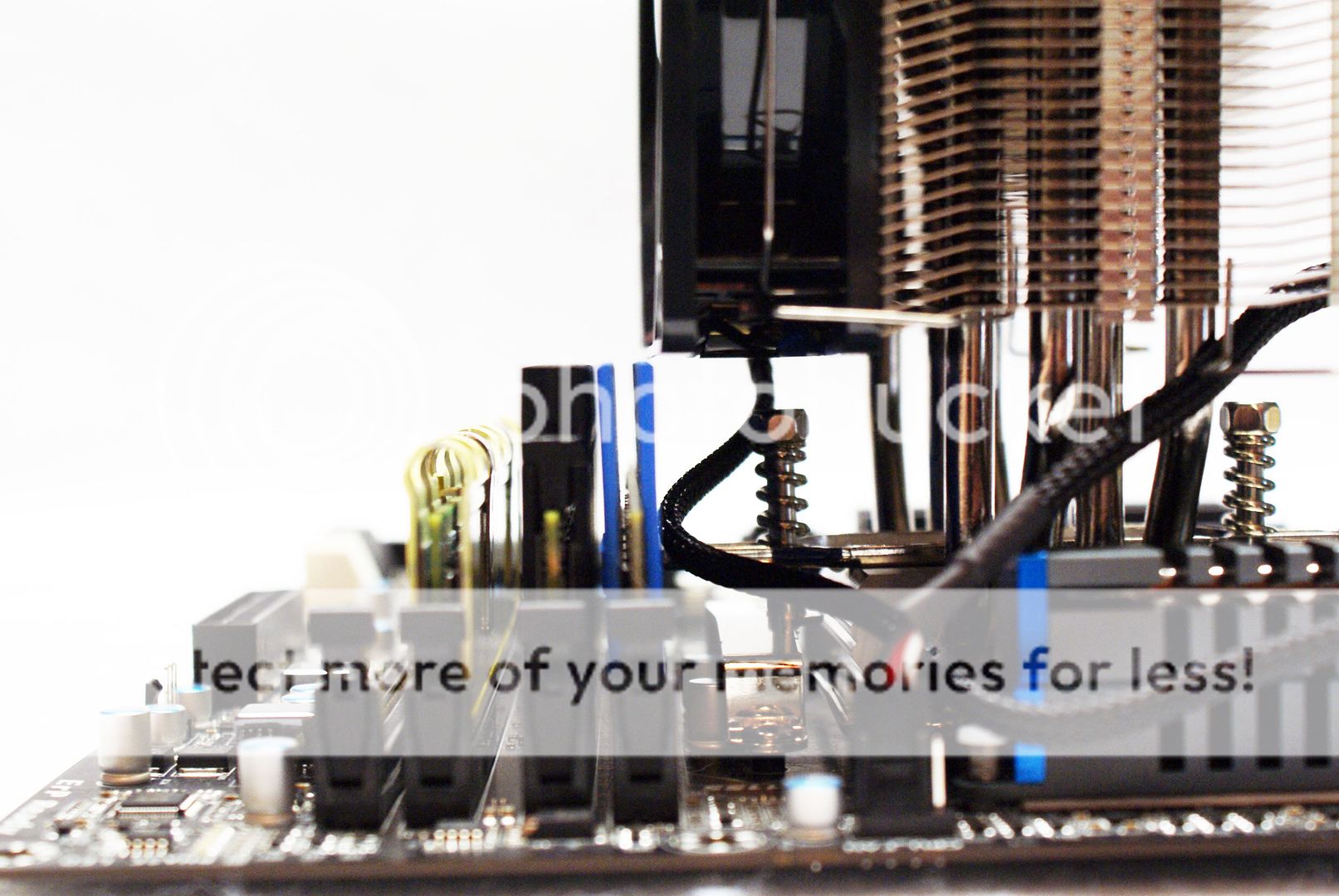
Here you can see the GA-P67A-UD4 in full, exhibiting the new matte black PCB from GIGABYTE. The color scheme is almost all black, having only a few blue accents on the heatsinks, which are designed in a shade of gray. On the SB heatsink in white is the GIGABYTE name, Ultra Durable is noted the I/O side mosfet heatsink, also in white. GIGABYTE used all black memory and PCI/PCIE slots to match the black PCB.

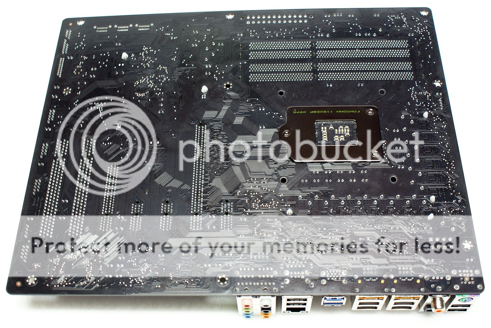
On the reverse you can see that plastic push-pins attach the mosfet and PCH heatsink. You can also see that the new matte black PCB from GIGABYTE is simply that, black, without ugly brown copper traces showing through. That brown showing through on many black PCB boards makes me cringe. GIGABYTE is on the right track with their implementation of black matte PCB.
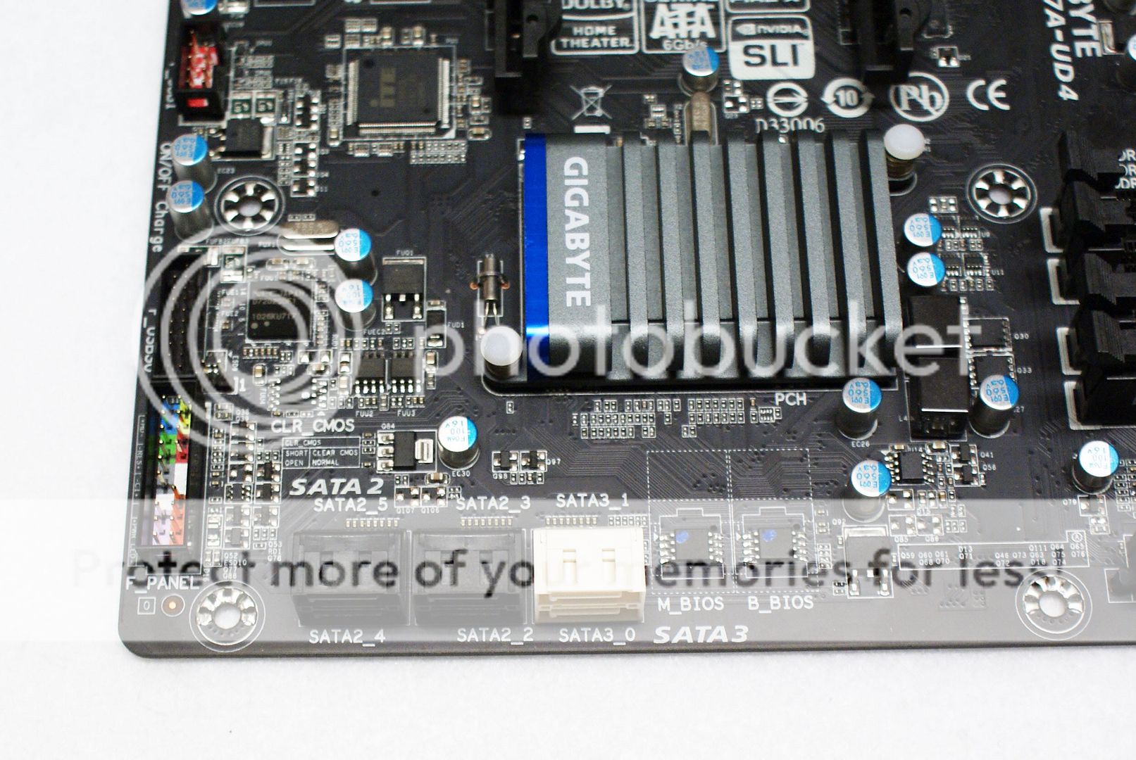

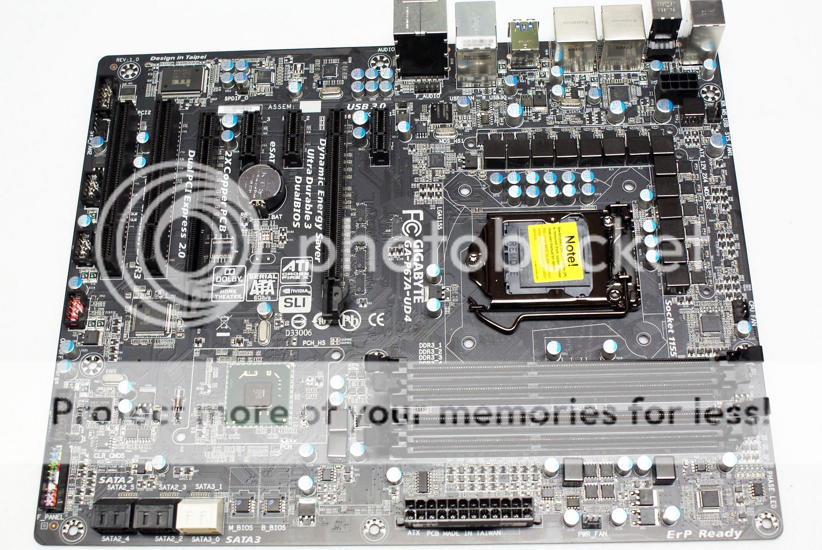
Here you can see the dual BIOS chips, and the 6 internal SATA ports. Two of the ports are 6GB/s Intel controlled ports, and the other four ports are Intel 3Gb/s, these latter 3Gb/s ports are those affected by the B2 chipset issues causing the recent recall by Intel. You can see there is a front USB 3.0 connector, however, there are no front panel USB 3.0 bay devices included with the motherboard. I am unsure how end users are supposed to take advantage of this feature, but it is nice to know it's there for future use.
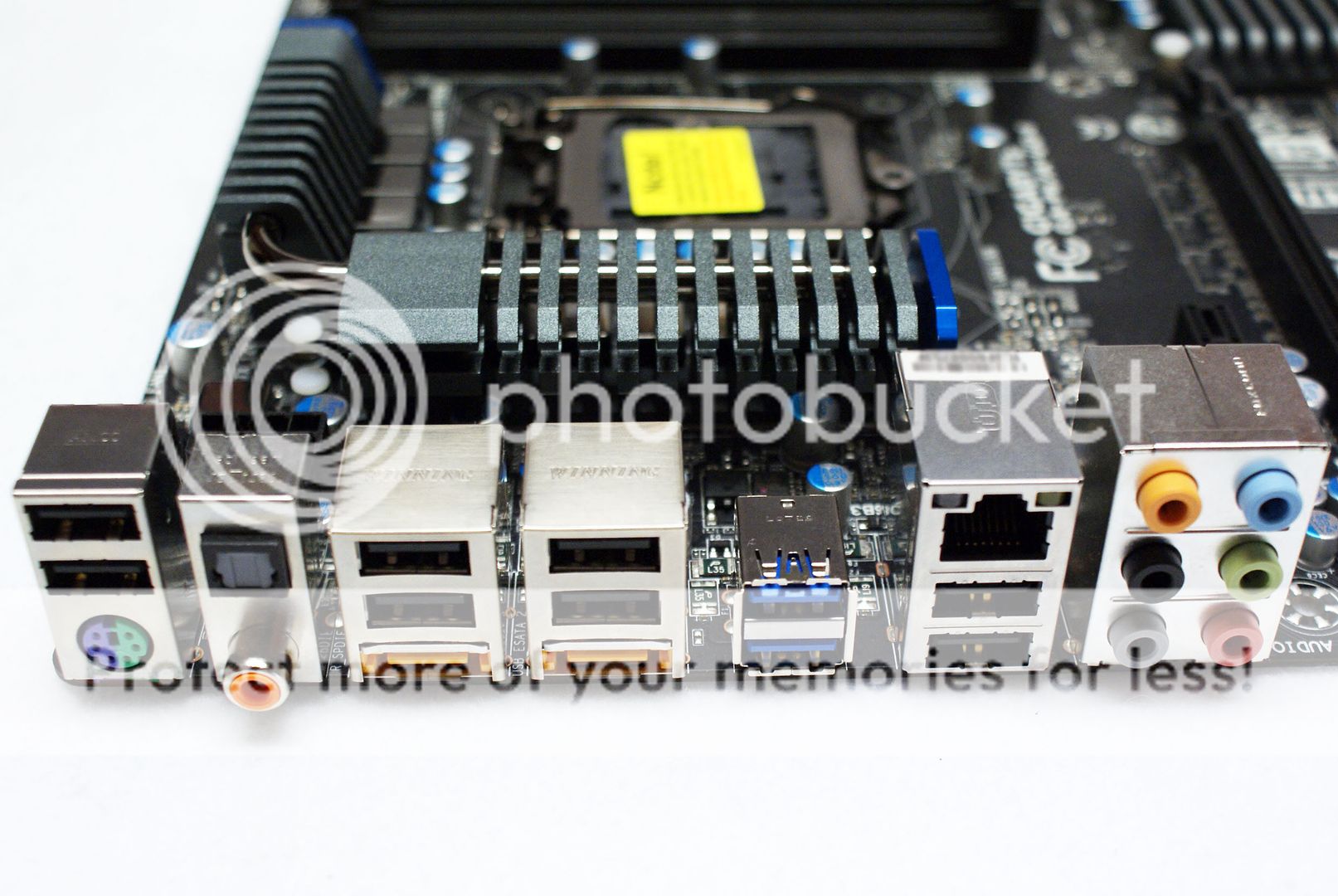
The I/O panel is feature full! Offering a mouse or keyboard PS2 connection, 1 optical and one coaxial S/PDIF connector, 8 USB 2.0/1.1 ports, 2 USB 3.0 ports, 2 eSATA 6Gb/s combo ports, one LAN connection, and 6 x audio connections supporting up to 7.1 channel HD audio.
Heatsinks Removed
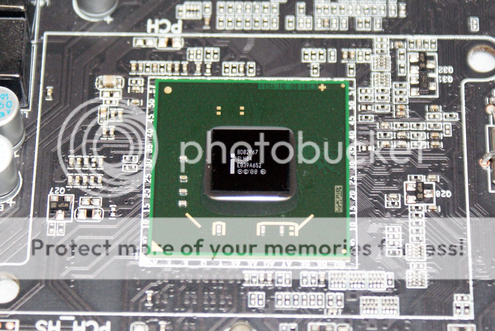

Here you can see the Intel P67 PCH chipset, and that the heatsinks and heatpipe combo has been removed. On the bottom we can see that pink thermal paste was used to secure the PCH heatsink to the P67 chip, this was very sticky and almost gum like. The heat from the driver mosfets is transferred to the heatsinks and heatpipe via thermal padding.
Here is full detailed shots of the board with the heatsinks removed, click to enlarge if you would like to see anything up close and personal. I do not have the technical skills to go in depth and discuss each IC or chip used on the board, but if you are interested or knowledgeable about these things and would like to know what products are used you can easily view them all from these images.


Here is the CPU socket area bare, you can see GIGABYTE's 12 Phase VRM power design for the CPU, and the new driver mosfets are also used. Noted on the reverse of the board you can see that this board uses an 4 layer PCB design.


Comment